Saturday, January 22, 2022

How To Calculate Reactor Jacket Volume

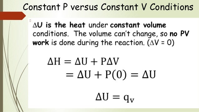
The choice between a jacket and coils is based on a number of considerations. For highly corrosive or highly reactive materials, a jacket has the advantage that there are no extra materials of construction and no extra metal surface in contact with the process other than the normal vessel wall. There is also less risk of cooling fluid coming into contact with the reaction mass. For the manufacture of pharmaceuticals, fine chemicals and performance products, a jacket minimizes contamination as there are no extra surfaces to clean. For materials with difficult rheology the full range of agitator designs can be used with a jacket without difficulty. However, a jacket has a lower heat transfer performance than a coil as there will be a lower process side coefficient, usually a greater wall thickness, and a smaller surface area.

how to calculate reactor jacket volume - The choice between a jacket and coils is based on a number of considerations

A jacket may also require a higher service side flow. For exothermic reactions, a jacketed vessel has the disadvantage that the area/volume ratio decreases with increasing scale. The use of a greater height/diameter ratio at larger scale can help to reduce this problem, but only to a limited extent. A coil has the advantage that a large surface area can be provided, for example, in one particular highly exothermic reaction 18 m2m−3 has been installed in a 5 m3 reactor. However, it is important not to pack the coil so tightly as to form a false wall.

how to calculate reactor jacket volume - For highly corrosive or highly reactive materials

The constant flux jacket has very fast temperature control response due to the short length of the flow channels and high velocity of the heat transfer fluid. Like the half coil jacket the heating/cooling flux is uniform. Because the jacket operates at substantially constant temperature however the inlet temperature oscillations seen in other jackets are absent. An unusual feature of this type jacket is that process heat can be measured very sensitively.

how to calculate reactor jacket volume - There is also less risk of cooling fluid coming into contact with the reaction mass

This allows the user to monitor the rate of reaction for detecting end points, controlling addition rates, controlling crystallization etc. It can be argued that heat transfer coefficient is also an important parameter. It has to be recognized however that large batch reactors with external cooling jackets have severe heat transfer constraints by virtue of design. It is difficult to achieve better than 100 Watts/litre even with ideal heat transfer conditions. By contrast, continuous reactors can deliver cooling capacities in excess of 10,000 W/litre. For processes with very high heat loads, there are better solutions than batch reactors.

how to calculate reactor jacket volume - For the manufacture of pharmaceuticals

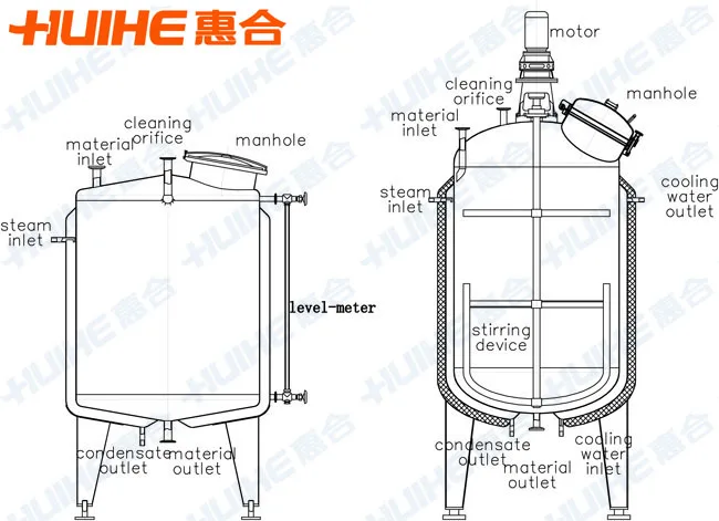
Products within batch reactors usually liberate or absorb heat during processing. Even the action of stirring stored liquids generates heat. In order to hold the reactor contents at the desired temperature, heat has to be added or removed by a cooling jacket or cooling pipe. Heating/cooling coils or external jackets are used for heating and cooling batch reactors. Heat transfer fluid passes through the jacket or coils to add or remove heat. The single jacket is probably the oldest design of external cooling jacket.

how to calculate reactor jacket volume - For materials with difficult rheology the full range of agitator designs can be used with a jacket without difficulty

Despite being a tried and tested solution, it has some limitations. On large vessels, it can take many minutes to adjust the temperature of the fluid in the cooling jacket. The distribution of heat transfer fluid is also far from ideal and the heating or cooling tends to vary between the side walls and bottom dish. Another issue to consider is the inlet temperature of the heat transfer fluid which can oscillate over a wide temperature range to cause hot or cold spots at the jacket inlet points. The coil has been sized on mean heat transfer values.

how to calculate reactor jacket volume - However

However, it may be better to size the control valve to supply the maximum (start-up) load. With large coils in tanks, this will help to maintain a degree of steam pressure throughout the length of the coil when the steam is turned on, helping to push condensate through the coil to the steam trapping device. If the control valve were sized on mean values, steam pressure in the coil at start-up will tend to be lower and the coil may flood. The half coil jacket is made by welding a half pipe around the outside of the vessel to create a semi circular flow channel.

how to calculate reactor jacket volume - A jacket may also require a higher service side flow

The heat transfer fluid passes through the channel in a plug flow fashion. A large reactor may use several coils to deliver the heat transfer fluid. Like the single jacket, the temperature in the jacket is regulated to control heating or cooling. The constant flux cooling jacket is a relatively recent development.

how to calculate reactor jacket volume - For exothermic reactions

It is not a single jacket but has a series of 20 or more small jacket elements. The temperature control valve operates by opening and closing these channels as required. By varying the heat transfer area in this way, the process temperature can be regulated without altering the jacket temperature. The plug flow characteristics of a half coil jacket permits faster displacement of the heat transfer fluid in the jacket . It also provides good distribution of heat transfer fluid which avoids the problems of non uniform heating or cooling between the side walls and bottom dish.

how to calculate reactor jacket volume - The use of a greater heightdiameter ratio at larger scale can help to reduce this problem

Like the single jacket design however the inlet heat transfer fluid is also vulnerable to large oscillations in temperature. The result is an increased conversion of reactant feed to product. Despite significant improvements in agitator blade and baffle design, mixing in large batch reactors is ultimately constrained by the amount of energy that can be applied. On large vessels, mixing energies of more than 5 Watts per litre can put an unacceptable burden on the cooling system. High agitator loads can also create shaft stability problems.

how to calculate reactor jacket volume - A coil has the advantage that a large surface area can be provided

Where mixing is a critical parameter, the batch reactor is not the ideal solution. Much higher mixing rates can be achieved by using smaller flowing systems with high speed agitators, ultrasonic mixing or static mixers. The batch reactor is the generic term for a type of vessel widely used in the process industries. In some cases, they are not referred to as reactors but have a name which reflects the role they perform .

how to calculate reactor jacket volume - However

The Wilson plot technique enables a deeper investigation of overall heat transfer coefficients, with very limited additional effort, if certain prerequisites are fulfilled. For stirred tank bioreactors, the required exponential relation between characteristic velocities and their corresponding heat transfer coefficients are available and thus, accessible for this approach. Strictly, the Wilson plot method only is valid for fully established turbulent flow. Further, for heat transfer with phase change, the thermal resistances of both sides cannot be considered independent and thus, further mathematical modifications are needed.

how to calculate reactor jacket volume - The constant flux jacket has very fast temperature control response due to the short length of the flow channels and high velocity of the heat transfer fluid

For further reading, the review of Fernández-Seara, et al. is recommended. Like the heat exchanger and gravity drained tanks case studies, the jacketed stirred reactor is a self regulating processes. That is, the measured process variable naturally seeks a steady operating level if the controller output and major disturbance are held constant for a sufficient length of time. A typical batch reactor consists of a storage tank with an agitator and integral heating/cooling system. These vessels may vary in size from less than 1 litre to more than 15,000 litres.

how to calculate reactor jacket volume - Like the half coil jacket the heatingcooling flux is uniform

They are usually fabricated in steel, stainless steel, glass-lined steel, glass or exotic alloy. Liquids and solids are usually charged via connections in the top cover of the reactor. Vapors and gases also discharge through connections in the top. As defined here generally represent a conjugate heat transfer process between two fluids through a wall. If such values are determined experimentally it might be desirable to deeper investigate the underlying processes.

how to calculate reactor jacket volume - Because the jacket operates at substantially constant temperature however the inlet temperature oscillations seen in other jackets are absent

One example might be the presence of a one-sided limitation, significantly reducing the overall heat transfer capabilities. Due to its nature, the overall heat transfer is limited by its least capable contributor, acting as insulation. Therefore, investigations targeting one sided heat transfer coefficients would require the other side to have infinite heat transfer capabilities. This would enable the direct calculation of the desired heat transfer coefficient.

how to calculate reactor jacket volume - An unusual feature of this type jacket is that process heat can be measured very sensitively

Although such results might have limited universality, studies in adequate models can simplify further scale-up. To stop the upward spiral of hotter temperatures increasing the rate of reaction that produces even more heat, the vessel is enclosed with a jacket . A cooling liquid flows through the jacket, collecting heat energy from the outer surface of the reactor vessel and carrying it away as the cooling liquid exits at the jacket outlet. Where α and αs are the process and service side heat transfer coefficients, respectively. The service side fouling resistance, l/αf, will be available from local experience or from Kern , for example.

how to calculate reactor jacket volume - This allows the user to monitor the rate of reaction for detecting end points

As a general guide, approximate overall coefficients typical of agitated jacketed vessels are given in Tables 1 and 2. When the flow of cooling liquid through the jacket increases, more heat is removed. This lowers the reactor temperature, slowing the rate of the reaction, and thus decreasing the amount of feed converted to product during passage through the reactor.

how to calculate reactor jacket volume - It can be argued that heat transfer coefficient is also an important parameter

And like the heat exchanger and the gravity drained tanks, the jacketed stirred reactor process is actually a sophisticated simulation derived from first-principles theory and available in commercial software. Nevertheless, the methods and procedures we establish during these investigations are directly applicable to a broad range of industrial processes with streams comprised of liquids, gases, powders, slurries and melts. The single jacket design consists of an outer jacket which surrounds the vessel.

how to calculate reactor jacket volume - It has to be recognized however that large batch reactors with external cooling jackets have severe heat transfer constraints by virtue of design

Heat transfer fluid flows around the jacket and is injected at high velocity via nozzles. The temperature in the jacket is regulated to control heating or cooling. However, with heat exchangers not designed to cope with the effects of waterlogging, this can lead to corrosion of the heating surface, inevitably reducing the service life of the exchanger.

how to calculate reactor jacket volume - It is difficult to achieve better than 100 Wattslitre even with ideal heat transfer conditions

Cold air at 4 °C flowing at 3 m/s can soon freeze condensate locked in the coils, resulting in premature and unwarranted failure. Proper drainage of condensate is essential to maintain the service life of any heat exchanger and air heater. For heat exchangers, any unwanted reduction in the heating surface area, such as that caused by condensate backing up into the steam space, can affect the flow of heat through the heating surface. This can cause the control system to become erratic and unstable, and processes requiring stable or accurate control can suffer with poor performance. However, further along the length of the coil the steam velocity may be lower, and the coil may be running partially full of water.

how to calculate reactor jacket volume - By contrast

In very long coils, such as those sometimes found in seagoing tankers or in large bulk storage tanks, a significant pressure drop occurs along the length of the coil. To achieve the mean coil temperature, an average steam pressure of approximately 75% of the inlet pressure may be used. In extreme cases the average pressure used may be as low as 40% of the inlet pressure. Estimates overall heat transfer coefficient for a vessel with an agitator along with heating/cooling medium flowing in jacket, jacket with spiral or half pipe coil. Because the reactor has a constant residence time, the amount of heat energy released inside the vessel is directly related to the percent of feed converted to product. By controlling the temperature in the reactor, we can maintain the percent conversion to the desired value.

how to calculate reactor jacket volume - For processes with very high heat loads

The chemical reaction releases heat and this energy causes the temperature of the material in the vessel to rise. As temperature rises, the conversion of feed to product proceeds faster, leading to the release of even more heat. The design and layout of the steam coil will depend on the process fluid being heated. This will ensure that there are no weak points in the tank lining, where there is a risk of leakage of corrosive liquids. In these cases the coil itself may also be made of corrosion resistant material such as lead covered steel or copper, or alloys such as titanium. The major disturbance in this jacketed stirred reactor is the result of an unfortunate design.

how to calculate reactor jacket volume - Products within batch reactors usually liberate or absorb heat during processing

Specifically, the temperature of the cooling liquid entering the jacket changes over time . As labeled in the figure , a reactant feed stream enters the top of the vessel. A chemical reaction converts most of this feed into the desired product as the material passes through what is essentially a stirred tank.

how to calculate reactor jacket volume - Even the action of stirring stored liquids generates heat

How To Calculate Minimum Stirrable Volume The stream exiting the bottom of the vessel includes the newly created product plus that portion of the feed that did not convert while in the vessel. If the steam trap is only sized on the first condition, it is possible that it may not pass the stall load . To calculate the heat transfer area, a value for the overall heat transfer coefficient, U, must be chosen. This will vary considerably with the thermal and transport properties of both fluids and a range of other conditions.

How To Calculate Minimum Stirrable Volume

Indirect heating of fluids is covered in this tutorial including layouts, control and drainage of coils and jackets, and heat transfer calculations. If it is desired that the heat transfer area must be provided as a jacket only. What changes in process design if any would you carry out?

how to calculate reactor jacket volume - Heatingcooling coils or external jackets are used for heating and cooling batch reactors

Show one set of calculation to illustrate your procedure. Example of a Wilson plot applied to a jacketed stirred tank reactor with the aim to determine the jacket side heat transfer coefficient by varying the stirring frequency. Critical pressure drop will occur across the control valve during start-up, therefore the minimum steam pressure in the heating coil should be taken as 58% of upstream absolute pressure. On the product side of the coil a thermal boundary layer will exist in which there is a temperature gradient between the surface and the bulk fluid. If this temperature difference is relatively large, then the natural convective currents will be significant and the heat transfer coefficient will be high.

how to calculate reactor jacket volume - Heat transfer fluid passes through the jacket or coils to add or remove heat

These are stationary blades which break up flow caused by the rotating agitator. These may be fixed to the vessel cover or mounted on the interior of the side walls. Further, the intercept represents the extrapolated point, where the process side thermal resistance approximates zero, representing a consistent graphical interpretation of the plot. However, the chart also shows that equidistant spacing of stirring frequencies during experimental determination might lead to unfavorable mathematical weighing of settings that show lower measurement accuracy. For example, in a tubular heat exchanger, higher fluid flow velocities often go along with lower measurable temperature differences and thus, are more impacted by noise.

how to calculate reactor jacket volume - The single jacket is probably the oldest design of external cooling jacket

As the temperature of the cooling liquid entering the jacket changes, so does its ability to remove heat energy. Warm liquid removes less energy than cool liquid when flowing through the jacket at the same rate. As shown in the figure below , the flow rate of cooling liquid is adjusted with a valve on the cooling jacket outlet stream. The conductivity of the wall material can be found in standard texts [Kern, ]. The resistance may be significant for some vessels linings, for example, glass lined steel, where the manufacturer's data should be consulted. There will also be some limitations on the ability of glass lining to withstand thermal shock.

how to calculate reactor jacket volume - Despite being a tried and tested solution

If heat exchangers are oversized, sufficient heating surface may remain when condensate backs up into the steam space, and reduction of thermal performance may not always occur. If one valve is to be used, this valve must ensure the maximum heat load is catered for, while maintaining the required steam pressure in the coil to assist the drainage of condensate from it at start-up. However, for reasons previously explained, two valves may be better. Maximum heat transfer will occur when the temperature difference between the steam and the process fluid is at its maximum, and should take into consideration the extra pipe area allowed for fouling. Tank coils are also extensively used in electroplating and metal treatment. Electroplating involves passing articles through several process tanks so that metallic coatings can be deposited on to their surfaces.

how to calculate reactor jacket volume - On large vessels

Submerged steam coils - A widely used form of heat transfer involves the installation inside a tank of a steam coil immersed in a process fluid. Will this calculation be applicable for agitated vessel. And also how can we say this heat transfer area for all, because we may have internal coil or limpet coil or simple jacket at that time also do we have same area. Estimate the reactor volume, conversion coolant flow rate at a time when 95 percent conversion is attained. The vessel is well mixed, so the bulk temperature inside the reactor is about the same as the temperature flowing out the exit stream.

how to calculate reactor jacket volume - The distribution of heat transfer fluid is also far from ideal and the heating or cooling tends to vary between the side walls and bottom dish

Friday, January 7, 2022

The Density Of Air At Stp Is 1 285 G L

Density Of Air At Stp G L Major geomagnetic storms are caused by unusually intense solar wind southward magnetic fields that impinge upon the Earth's magnetosphere . How can we predict the occurrence of future interplanetary events? Do we currently know enough of the underlying physics and do we have sufficient observations of solar wind phenomena that will impinge upon the Earth's magnetosphere? We view this as the most important challenge in space weather. We discuss the case for magnetic clouds , interplanetary sheaths upstream of interplanetary coronal mass ejections , corotating interaction regions and solar wind high-speed streams . The sheath- and CIR-related magnetic storms will be difficult to predict and will require better knowledge of the slow solar wind and modeling to solve.

Density Of Air At Stp G L

For interplanetary space weather, there are challenges for understanding the fluences and spectra of solar energetic particles . This will require better knowledge of interplanetary shock properties as they propagate and evolve going from the Sun to 1 AU , the upstream slow solar wind and energetic "seed" particles. Dayside aurora, triggering of nightside substorms, and formation of new radiation belts can all be caused by shock and interplanetary ram pressure impingements onto the Earth's magnetosphere. The forecasting of extreme events (extreme shocks, extreme solar energetic particle events, and extreme geomagnetic storms ) are also discussed. Energetic particle precipitation into the atmosphere and ozone destruction are briefly discussed. For many of the studies, the Parker Solar Probe, Solar Orbiter, Magnetospheric Multiscale Mission , Arase, and SWARM data will be useful.

the density of air at stp is 1 285 g l - How can we predict the occurrence of future interplanetary events

Interplanetary shocks have a variety of effects on both interplanetary space and the Earth's magnetosphere. It is important for the reader to note that these space weather phenomena can occur with or without the occurrence of magnetic storms. Shock and magnetic storm intensities are related, but only in a loose sense. The physical mechanisms for energy transfer for different phenomena are different. Solar cosmic ray events can occur with or without magnetic storms (Halford et al., 2015, 2016; Mays et al., 2015; Foster et al., 2015). Some of the major extreme space weather topics will be addressed below.

the density of air at stp is 1 285 g l - Do we currently know enough of the underlying physics and do we have sufficient observations of solar wind phenomena that will impinge upon the Earth

When a shock is formed, it compresses the upstream plasma and magnetic fields. The compressed plasma and magnetic fields downstream of the shock are the "sheath". The shock and sheath are not part of the CME/ICME.

the density of air at stp is 1 285 g l - We view this as the most important challenge in space weather

The origin of these plasma and magnetic fields is the slow solar wind altered by shock compression. This is important to understand if one wishes to predict magnetic storms caused by interplanetary sheath southward magnetic fields. It should be noted that "slow" ICMEs have been detected at 1 AU (Tsurutani et al., 1994a).

the density of air at stp is 1 285 g l - We discuss the case for magnetic clouds

These phenomena do not have upstream shocks and sheaths, as expected. However, the southward MC magnetic fields still cause magnetic storms. Several spacecraft missions have been mentioned in relation to some forecasting problems. However, the reader should note that the missions and/or their data alone will not solve these problems.

the density of air at stp is 1 285 g l - The sheath- and CIR-related magnetic storms will be difficult to predict and will require better knowledge of the slow solar wind and modeling to solve

It will either be the scientists on these missions or perhaps totally independent scientists who will make the most progress on these problems. An example is magnetic storms caused by interplanetary shocks/sheaths and CIRs. How long will it take scientists to be able to accurately forecast the time of occurrence of the storm and the intensity ? Here we will not make an estimate of how long this will take.

the density of air at stp is 1 285 g l - For interplanetary space weather

Shock acceleration of solar flare particles is clearly a fundamental part of space weather. How long will scientists take to be able to predict the fluence and spectral shape at a variety of distances away from the Sun? This is a fundamental problem which space agencies are not currently directly addressing.

the density of air at stp is 1 285 g l - This will require better knowledge of interplanetary shock properties as they propagate and evolve going from the Sun to 1 AU

With the advent of rockets and satellites, the near-Earth interplanetary medium has been probed by magnetic field, plasma, and energetic particle detectors. The Sun has been viewed at many different wavelengths. The Earth's auroral regions have recently been viewed by UV imagers, giving a global view of auroras including the dayside. The most useful part of this review will be to focus on what future advances in space weather might be in the next 10 to 25 years. In particular, we will mention which outstanding problems the Parker Solar Probe, Solar Orbiter, MMS, Arase, ICON, GOLD, and SWARM data might be useful in solving. From the geomagnetic equator , the lowest in recorded history.

the density of air at stp is 1 285 g l - Dayside aurora

Since this event has been used as an example of extreme space weather and events of this type are a problem for U.S. Homeland Security, we felt that there should be a separate section on this topic, Sect. We also discuss the possibility of events even larger than the Carrington storm occurring. Why is this topic covered in this paper?

the density of air at stp is 1 285 g l - The forecasting of extreme events extreme shocks

Section 9 gives our summary/conclusions for the physics and the possibility of forecasting space weather events. Section 10 is a glossary of space weather terms used by researchers in the field. Most of the definitions were carefully constructed in a previous book . These should be useful for an ionospheric researcher looking up solar terms.

the density of air at stp is 1 285 g l - Energetic particle precipitation into the atmosphere and ozone destruction are briefly discussed

It could be particularly useful for the non-space plasma readership as well. In the magnetosphere, a region of current that flows near the geomagnetic equator in the outer belt of the two Van Allen radiation belts. The current is produced by the gradient and curvature drift of the trapped charged particles of energies of 10 to 300 keV. The ring current is greatly augmented during magnetic storms because of the hot plasma injected from the magnetotail and upwelling oxygen ions from the ionosphere. Further acceleration processes bring these ions and electrons up to ring current energies.

the density of air at stp is 1 285 g l - For many of the studies

The ring current causes a worldwide depression of the horizontal geomagnetic field during a magnetic storm. During the declining phase of the solar cycle a different type of solar and interplanetary activity dominates the physical cause of magnetic storms, that of corotating interaction regions . HSSs emanating from coronal holes interact with the slow solar wind and form CIRs at their interaction interfaces. The magnetic storms caused by CIRs are quite different from storms caused by ICMEs and/or their sheaths.

the density of air at stp is 1 285 g l - Interplanetary shocks have a variety of effects on both interplanetary space and the Earth

Figure 6 shows the difference in profiles of two different types of magnetic storms. The profile of a CIR magnetic storm is shown at the bottom and that of a shock sheath ahead of an ICME MC magnetic storm on top. It should be noted that a fast reverse wave (here by "reverse" we mean that the wave is propagating in the solar direction) was detected during the Fig. It is identified as the red vertical line on 8 November. This reverse wave caused a decrease in the MC magnetic field and thus the start of the recovery phase of the magnetic storm. The reader should note that fast reverse waves and shocks are also important for geomagnetic activity.

the density of air at stp is 1 285 g l - It is important for the reader to note that these space weather phenomena can occur with or without the occurrence of magnetic storms

A detailed discussion of shock and discontinuity effects on geomagnetic activity can be found in Tsurutani et al. . Regions of the magnetosphere roughly 1.2 to 6 Earth radii above the equator in which charged particles are stably trapped by closed geomagnetic field lines. The inner belt's maximum proton density lies near 5000 km above the Earth's surface. Inner belt protons and electrons originate from the decay of secondary neutrons created during collisions between cosmic rays and upper atmospheric particles.

the density of air at stp is 1 285 g l - Shock and magnetic storm intensities are related

The outer belt extends on to the magnetopause on the sunward side and to about 6 Earth radii on the nightside. The altitude of maximum proton density is near – km. Outer belt protons and electrons are lower energy . The origin of the particles is a mixture of the solar wind and the ionosphere. The outer belt is also characterized by highly variable fluxes of energetic electrons.

the density of air at stp is 1 285 g l - The physical mechanisms for energy transfer for different phenomena are different

The radiation belts are often called the "Van Allen radiation belts" because they were discovered in 1958 by a research group at the University of Iowa led by Professor J. A. Van Allen. NT) magnetic storms that occurred during solar cycle 23. The solar wind drags the interconnected magnetic fields and plasma downstream . The open magnetic fields then reconnect in the tail. Reconnection leads to strong convection of the plasma sheet into the nightside magnetosphere.

the density of air at stp is 1 285 g l - Solar cosmic ray events can occur with or without magnetic storms Halford et al

A visual phenomenon that occurs mainly in the high-latitude night sky. Auroras occur within a band of latitudes known as the auroral oval, the location of which is dependent on the intensity of geomagnetic activity. Auroras are a result of collisions between precipitating charged particles and atmospheric atoms and molecules, exciting the atmospheric constituents. The charged particles come from the outer parts of the magnetosphere and are guided by the geomagnetic field. Each gas emits its own characteristic radiation when bombarded by the precipitating particles. The auroral altitude range is 80 to 500 km, but typical auroras occur 90 to 250 km above the ground.

the density of air at stp is 1 285 g l - Some of the major extreme space weather topics will be addressed below

The color of the typical aurora is yellow–green, from a specific transition line of atomic oxygen. Auroral light from lower levels in the atmosphere is dominated by blue and red bands from molecular nitrogen and molecular oxygen. Above 250 km, auroral light is characterized by a red spectral line of atomic oxygen.

the density of air at stp is 1 285 g l - When a shock is formed

To an observer on the ground, the combined light of these three fluctuating primary colors produces an extraordinary visual display. Auroras in the Northern Hemisphere are called the aurora borealis or "northern lights". Auroras in the Southern Hemisphere are called the aurora australis. The patterns and forms of the aurora include quiescent "arcs", rapidly moving "rays" and "curtains", "patches", and "veils". However, the fundamental issue of space weather prediction for magnetic storms is the direction and intensity of the magnetic field in both the MC and upstream sheath.

the density of air at stp is 1 285 g l - The compressed plasma and magnetic fields downstream of the shock are the sheath

These topics still remain a challenge. These Mach numbers get close to expected supernova shock values. Why have such strong shocks not been observed at 1 AU? If such events are possible, what would the energetic particle fluences be? Experts on shock particle acceleration will hopefully answer this complex question. It is well known that such solar flare particles enter the polar regions of the Earth's atmosphere and cause radio blackouts.

the density of air at stp is 1 285 g l - The shock and sheath are not part of the CMEICME

Will extreme solar flare particle fluence precipitation cause different ionospheric effects other than those known today? This latter question might be addressed by ionospheric modelers. Corotating interaction region .

the density of air at stp is 1 285 g l - The origin of these plasma and magnetic fields is the slow solar wind altered by shock compression

An interplanetary region of high magnetic fields and plasma densities created by the interaction of a high-speed solar wind stream with the upstream slow solar wind. The antisunward portion of the CIR is compressed slow solar wind plasma and magnetic fields, and the sunward portion is compressed fast solar wind plasma and magnetic fields. The two regions of the CIR are separated by a tangential discontinuity.

the density of air at stp is 1 285 g l - This is important to understand if one wishes to predict magnetic storms caused by interplanetary sheath southward magnetic fields

The concept of magnetic reconnection is introduced first for the non-space plasma reader. Magnetic reconnection is the physical process responsible for transferring solar wind energy into the magnetosphere during magnetic storms. We have organized the rest of the paper by discussing space weather phenomena by solar cycle intervals.

the density of air at stp is 1 285 g l - It should be noted that slow ICMEs have been detected at 1 AU Tsurutani et al

However, it should be mentioned that this is not totally successful since some phenomena span all parts of the solar cycle. Extremely energetic charged particles or electromagnetic radiation, primarily originating outside of the Earth's magnetosphere. Cosmic rays usually interact with the atoms and molecules of the atmosphere before reaching the surface of the Earth. The nuclear interactions lead to formation of daughter products, and they in turn to granddaughter products, etc. Thus, there is a chain of reactions and a "cosmic ray shower". Some cosmic rays come from outside the solar system, while others are emitted from the Sun in solar flares.

the density of air at stp is 1 285 g l - These phenomena do not have upstream shocks and sheaths

See also Anomalous cosmic ray, Energetic particle, and Solar energetic particle event. This is a very difficult task since knowledge of the entire slow solar wind plasma from the Sun to 1 AU will be required for accurate forecasting. But again, the Parker Solar Probe and Solar Orbiter may help in developing two points of measurements for modeling of specific events. There are many important questions about PPEFs which are almost always present during major magnetic storms. As previously mentioned, "why are the electric fields not shielded out?

the density of air at stp is 1 285 g l - However

" What is the mechanism for generating PPEFs, wave propagation from the polar ionosphere as suggested by Kikuchi and Hashimoto or a more global picture as Fig. 25 and Nishida and Jacobs suggest? Figure 25 is a simple schematic. What are the real local time dependences of the PPEF? Does this vary from storm to storm, and if so, why? Why does the relative PPEF magnitude vary from one storm to the next?

the density of air at stp is 1 285 g l - Several spacecraft missions have been mentioned in relation to some forecasting problems

Again, future spacecraft and ground-based studies will be able to help answer these questions. This figure is a superposed epoch analysis , the result of 35 HILDCAA events in solar cycle 23, from 1995 to 2008, which are not preceded by magnetic storms. The exclusion of magnetic storms was done to avoid contamination by storm-time particle acceleration (by intense convection/compression). The zero-epoch time corresponds to the HILDCAA onset time. Here the "strict" definition of HILDCAAs was used to define the onset times. A shock wave is characterized by a discontinuous change in pressure, density, temperature, and particle streaming velocity, propagating through a compressible fluid or plasma.

the density of air at stp is 1 285 g l - However

Fast collisionless shock waves occur in the solar wind when fast solar wind overtakes slow solar wind, with the difference in speeds being greater than the magnetosonic speed. Collisionless shock thicknesses are determined by the proton and electron gyroradii rather than the collision lengths. See also Diffusive shock acceleration and Solar wind shock. Details concerning the shocks and compressions can be found in the original paper for readers who are interested.

the density of air at stp is 1 285 g l - It will either be the scientists on these missions or perhaps totally independent scientists who will make the most progress on these problems

What is important here is how intense interplanetary magnetic fields are created. They can come from the MCs themselves or the sheaths, as shown here. However, in this case the southward magnetic fields that caused the magnetic storm came from the MC and not the sheath.

the density of air at stp is 1 285 g l - An example is magnetic storms caused by interplanetary shockssheaths and CIRs

What Is The Meaning Of Relation To Student

We will then apply Relationship-Centered Care principles to the student-teacher relationship. We conclude by making suggestions for future r...